Embedded Programming
Overview of week 4
Group Assignment
Demonstrate and compare the toolchains and development workflows for available embedded architectures.
Individual Assignments
Browse through the data sheet for our microcontroller write a program for a microcontroller, and simulate its operation, to interact (with local input &/or output devices) and communicate (with remote wired or wireless connections).
Group Assignment :
For the group assigment I used the XIAO-ESP32-C3 board and one LED and resistor, by using the VS code I made the LED blink.
I learnt about how to do the code compiling and uploading on the various microcontrollers
Individual Assignment :
Arduino
Arduino is an open-source electronics platform with hardware and software designed for ease of use. It features microcontroller-based boards like Arduino Uno (ATmega328P) and supports C/C++ programming. The Arduino IDE simplifies coding and uploading programs. It interfaces with sensors, LEDs, motors, and other components. Its open-source nature allows customization and improvements. With extensive community support, it is widely used in education, prototyping, and IoT projects.
In my exploration, I am using the Arduino Uno, which has allowed me to learn basic simulations in software platforms.
ATmega328P
The ATmega328P is an 8-bit AVR microcontroller developed by Microchip Technology. It is widely used in embedded systems.
Specification
- Architecture: 8-bit AVR RISC
- Clock Speed: Up to 20 MHz (16 MHz in Arduino Uno)
- Flash Memory: 32 KB (for storing programs)
- EEPROM: 1 KB (for non-volatile data storage)
- GPIO Pins: 23 I/O pins (including 6 PWM and 6 ADC channels)
- Communication Interfaces: UART, SPI, I2C
Datasheet
I first reviewed the table of contents of the datasheet to understand the document structure. I observed sections related to pin configuration, memory organization, timers, ADC, communication protocols, interrupts, electrical characteristics, and power management.
It helps quickly locate information during hardware design and debugging.
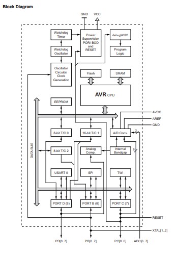
Block diagram
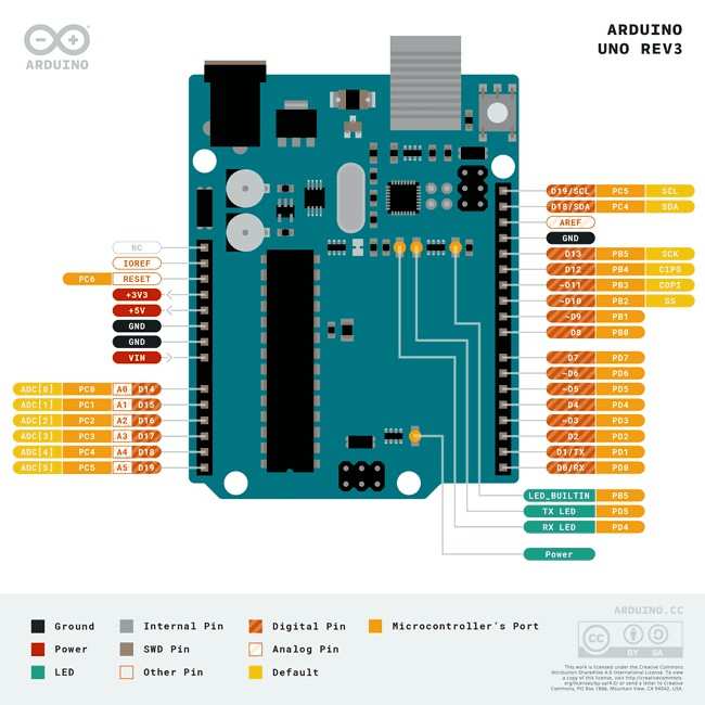
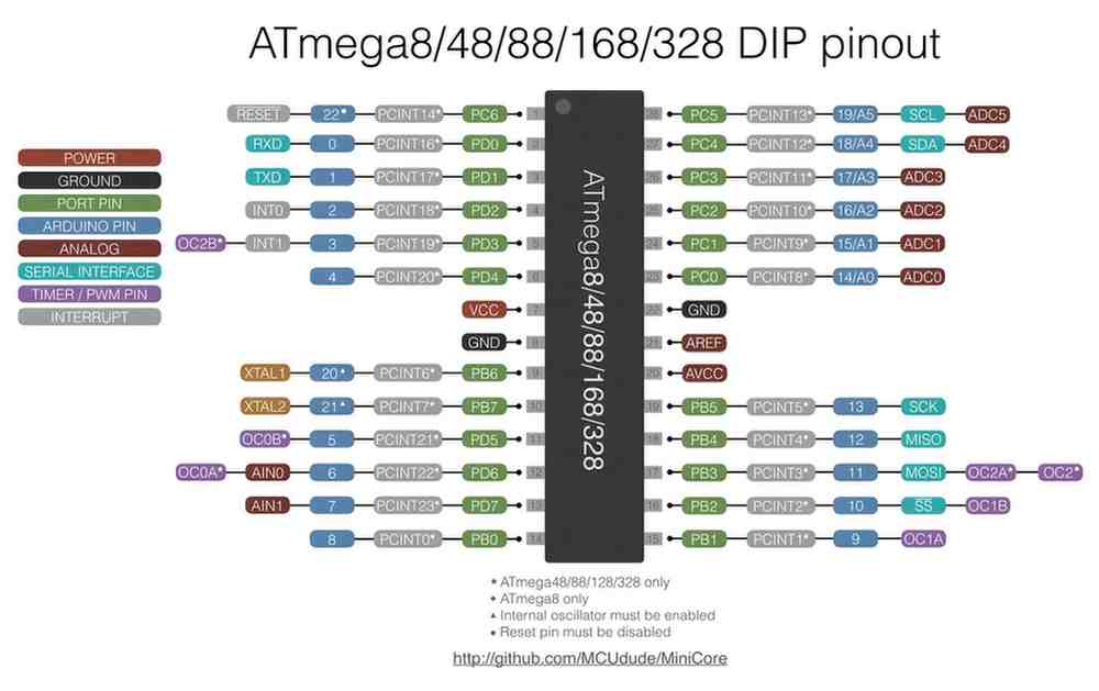
Pin Configuration
I explored the pinout diagram and identified:
AVR Memories
I checked the memory section,I learned that:
For instant if I create a project to control an LED using a push button,
Electrical Characteristics
I explored:I also learned that the microcontroller interprets voltages close to 5V as HIGH (logic 1) and voltages close to 0V as LOW (logic 0). This is how the microcontroller determines whether a button is pressed or an LED should be turned ON or OFF.
Understanding the electrical characteristics helps me select appropriate components, design safe circuits, and prevent damage to the microcontroller during hardware development and testing.
ADC Section
I explored the ADC chapter and found:For instant
Tinkercad
Tinkercad is a free, web-based platform by Autodesk for 3D design, circuit simulation, and Arduino coding. It allows users to create 3D models, simulate electronic circuits, and program Arduino using block or text-based coding. With a user-friendly interface, it is ideal for beginners in electronics, robotics, and design. No installation is needed, as it runs directly in a web browser.
I used Tinkercad for basic Arduino simulations. I explored the interface of tinkercad and got some ideas how to do the Components arrangements, connections btw the others, coding and simulations.
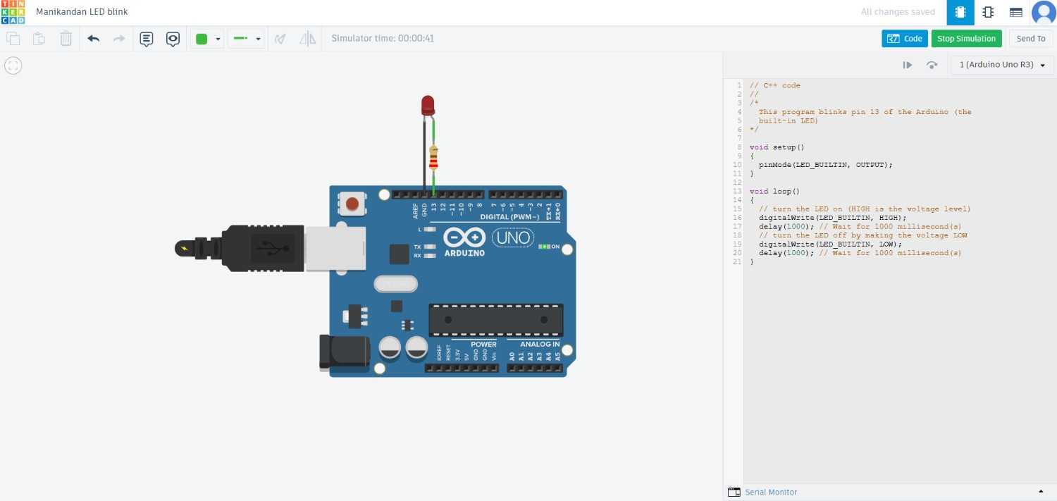
LED blink
First i did the basic simulation of LED blink, I take the arduino in the library and also collect the LED and resistor, Connect them as per the code which is I given in the Coding interface.
void setup()
{
  pinMode(LED_BUILTIN, OUTPUT);
}
void loop()
{
  digitalWrite(LED_BUILTIN, HIGH);
  delay(1000);
  digitalWrite(LED_BUILTIN, LOW);
  delay(1000);
}
- void setup() is a function, whenever the Arduino is powered on or reset it will run. It is used to set the initial configurations like pin modes.
- In pinMode we can set the LED pin as an output.
- void loop() is a function which can runs repeatedly in a loop after one another
- By using the digitalWrite we can turns on & off the LED by sending a HIGH signal (5V) and LOW signal (0V) to the LED pin.
- delay() function is used to describe our works within the time frame, here I used the 1000 milliseconds, after every that seconds LED will blink.
LCD Display
After that I do the simulations with utilize the LCD display,
Adafruit_LiquidCrystal lcd(0);

void setup()
{
  lcd.begin(16, 2);
  lcd.setCursor(1,0);
  lcd.print("Fablab  Trichy");
}
void loop()
{
  lcd.setBacklight(1);
  delay(100);
  lcd.setBacklight(0);
  delay(10);
}
- Here I used the Adafruit_LiquidCrystal library to control the LCD display
- In lcd.begin we should initializes the LCD with 16 columns and 2 rows like what type of Display is that.
- I set the lcd.setCursor as the cursor position to column 1, row 0.
- To display the text "Fablab Trichy" we can use the lcd.print starting from the current cursor position on the LCD.
- For blinking the display I set the lcd.setBacklight() 1 &0 for turn on and off the LCD display light.
Servo mechanism
Further I did the Servo actuation by controlling the code as well
#include <Servo.h>
int pos = 0;
Servo servo_10;
void setup()
{
  servo_10.attach(2, 500, 2500);
}
void loop()
{
  for (pos = 0; pos <= 90; pos += 1) {
    servo_10.write(pos);
    delay(1);
  }
}
- I included the<Servo.h> to control the servo motor
- To declares an integer variable named as pos and initializes it to 0.
- In servo_10.attach(2, 500, 2500) we can set the minimum and maximum pulse widths (in microseconds). 2 is the Digital pin and where 500 and 2500 refers 500 μs ≈ 0°, 2500 μs ≈ 180°.
ESP
ESP (Espressif Systems) is a series of low-power microcontrollers widely used in IoT applications. It offers built-in Wi-Fi and Bluetooth connectivity, making it ideal for wireless communication. ESP modules support multiple programming environments, including Arduino, MicroPython, and ESP-IDF. They are known for their high performance, low power consumption, and cost-effectiveness. ESP microcontrollers integrate various peripherals such as ADC, DAC, PWM, and GPIOs. They are commonly used in smart home devices, automation, and embedded systems. The most popular models include ESP8266 and ESP32, with ESP32 offering enhanced features like dual-core processing.
I explored ESP32 microcontrollers and gained knowledge that may make it a suitable choice for my final project.
ESP32
The ESP32 is a powerful Wi-Fi and Bluetooth-enabled microcontroller developed by Espressif Systems. It features a dual-core 32-bit Xtensa LX6 processor, running up to 240 MHz, with 520 KB SRAM and 4 MB flash memory (varies by model). It supports Wi-Fi (802.11 b/g/n), Bluetooth 4.2/BLE, GPIOs, ADC, DAC, SPI, I2C, UART, and PWM. Known for its low power consumption and high performance, it is widely used in IoT, robotics, automation, and embedded systems.
Specification
- Architecture: 32-bit Xtensa LX6 (dual-core)
- Clock Speed: Up to 240 MHz
- Flash Memory: Up to 16 MB (varies by model)
- SRAM: 520 KB (internal)
- GPIO Pins: Up to 34 I/O pins
- ADC: 18 channels (12-bit resolution)
- DAC: 2 channels (8-bit resolution)
- Communication Interfaces: UART, SPI, I2C, I2S, CAN, PWM
- Wireless Connectivity: Wi-Fi (802.11 b/g/n), Bluetooth 4.2 + BLE
- Operating Voltage: 3.3V
Datasheet
ESP32 Block Diagram
I explored the ESP32 block diagram section.The block diagram shows how different internal components are connected inside the microcontroller. For example, the CPU communicates with memory, peripherals, and wireless modules to execute programs and process data.
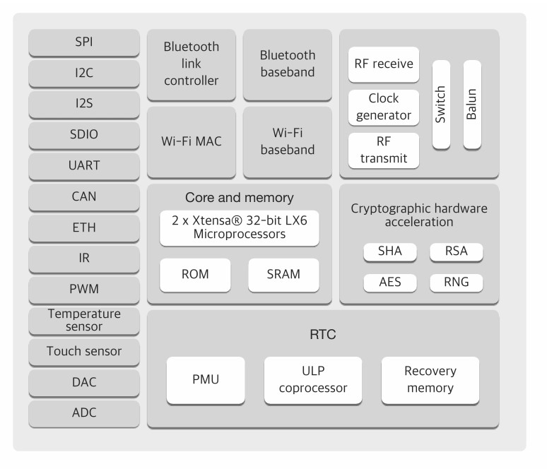
The block diagram helps me understand the internal architecture of the ESP32 and how different subsystems work together.
GPIO and Pin Functions
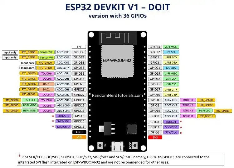
It helps identify which pins can be used for sensors, actuators, and communication interfaces.
Memory Organization
Understanding memory organization helps me know where code and data are stored inside the microcontroller. It also helps in optimizing memory usage and troubleshooting issues related to program storage and runtime memory limitations.
Wi-Fi and Bluetooth Features
ADC Section
It helps in reading analog signals from sensors and measuring varying voltage levels accurately.
Communication Interfaces
I explored the Communication Interfaces section of the ESP32 datasheet. This section describes how the ESP32 exchanges data with external devices and other microcontrollers.UART (Universal Asynchronous Receiver Transmitter)
UART is a serial communication protocol that uses two wires:
SPI (Serial Peripheral Interface)
SPI is a high-speed communication protocol that uses:
I2C (Inter-Integrated Circuit)
I2C is a communication protocol that uses only two wires:
I2S (Inter-IC Sound)
I2S is a digital audio communication protocol.
It is used to connect microphones, audio codecs, and speakers for audio processing applications.
By these we learned how the ESP32 can communicate with sensors, displays, memory modules, audio devices, and other microcontrollers in embedded system applications.
Seeed studio
Seeed Studio is a hardware innovation platform that provides open-source electronic modules, development boards, and IoT solutions. It offers products like Seeeduino (Arduino-compatible boards), Grove sensors, XIAO microcontrollers, and Edge AI solutions. Known for its rapid prototyping, industrial IoT, and AI hardware, Seeed Studio supports makers, students, and engineers in building embedded systems and smart devices.
Furthermore, I explored this in greater depth and practiced working with it.
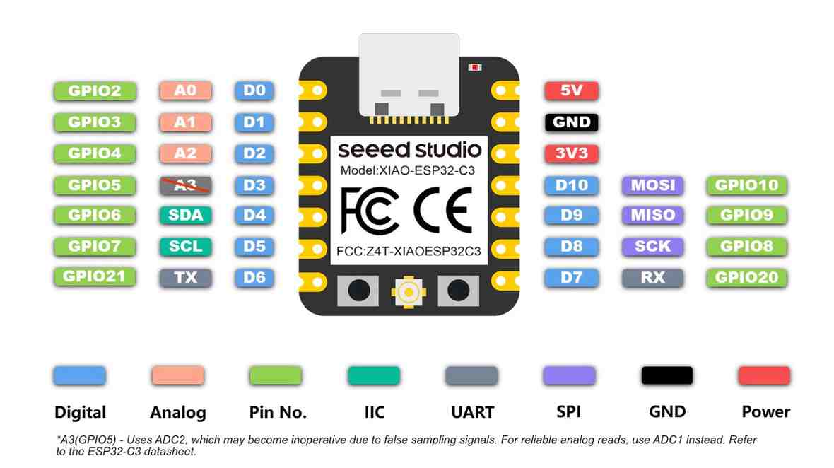
XIAO-ESP32-C3
The Seeed Studio XIAO ESP32-C3 is a compact Wi-Fi + Bluetooth 5 (BLE) microcontroller based on the ESP32-C3 (RISC-V single-core CPU @160 MHz). It features 4 MB Flash, 400 KB SRAM, and supports GPIO, ADC, PWM, UART, SPI, and I2C. With its small size (21×17.5 mm), low power consumption, and Type-C USB, it is ideal for IoT, wearables, and edge computing applications.
Specification
- Architecture: 32-bit RISC-V (single-core)
- Architecture: 32-bit RISC-V (single-core)
- Clock Speed: Up to 160 MHz
- Flash Memory: 4 MB
- SRAM: 400 KB
- GPIO Pins: 11 I/O pins (supports ADC, PWM, I2C, SPI, UART)
- Wireless Connectivity: Wi-Fi (802.11 b/g/n, 2.4 GHz), Bluetooth 5 (BLE)
- USB Interface: USB Type-C (native)
- Operating Voltage: 3.3V
- Dimensions: 21 × 17.5 mm
Datasheet
Wi-Fi and Bluetooth Low Energy (BLE)
I explored the wireless communication section of the datasheet.It helps me understand the wireless capabilities available for IoT and remote monitoring applications.
USB Serial/JTAG Controller
I found that the ESP32-C3 includes a built-in USB Serial/JTAG controller.The microcontroller can be programmed and debugged directly through the USB Type-C connection without requiring an external USB-to-UART converter.
This simplifies programming, debugging, and firmware uploading during embedded system development.
GPIO Matrix and Peripheral Routing
I found that many peripheral signals can be mapped to different GPIO pins through the GPIO Matrix.Communication peripherals such as UART, SPI, and I2C are not always fixed to specific pins and can often be assigned to different GPIOs.
This provides greater flexibility when designing custom PCBs and connecting external devices.
Security Features
These features help protect embedded systems from unauthorized firmware modifications and improve device security.
Low-Power Features
Multiple power-saving modes designed to reduce energy consumption. The ESP32-C3 can enter sleep modes when inactive and wake up when an event occurs.This is important for battery-powered IoT devices where power efficiency is critical.
Wokwi
Wokwi is a web-based electronics simulator for Arduino, ESP32, Raspberry Pi, and AVR microcontrollers. It allows users to write, test, and debug embedded code in real time without physical hardware. The platform supports sensors, displays, motors, and communication modules. It is ideal for IoT, robotics, and embedded systems development.
Using this, I conducted two simulations with different boards: ESP32 and XIAO-ESP32-C3.
ESP32 with OLED display
I used an OLED display to obtain output with the ESP32, programming it in MicroPython.
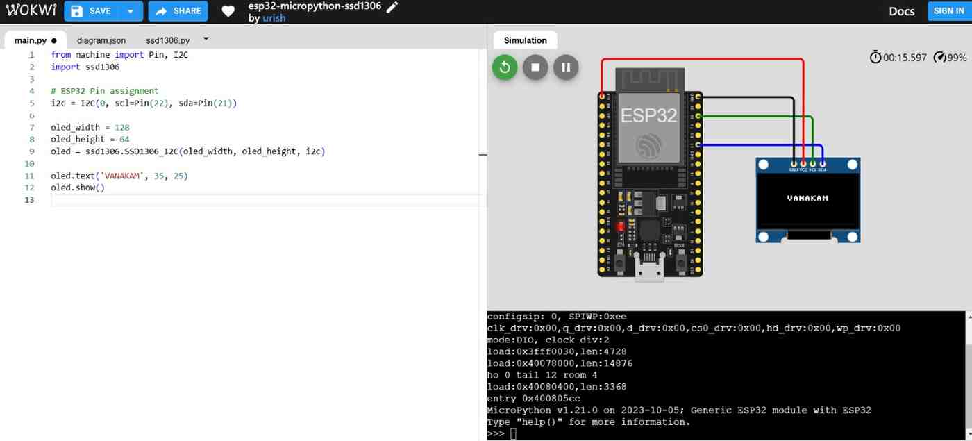
from machine import Pin, I2C
import ssd1306

# ESP32 Pin assignment
i2c = I2C(0, scl=Pin(22), sda=Pin(21))

oled_width = 128
oled_height = 64
oled = ssd1306.SSD1306_I2C(oled_width, oled_height, i2c)

oled.text('VANAKAM', 35, 25)
oled.show()
- I Imports the ssd1306 library to control SSD1306 OLED displays.
- In i2c we should set the Pins for scl and sda , scl is the clock pin and sda is the dat pin
- Further I set the oled display height and width.
- In oled.text we will show the text and set the dimension as well
XIAO-ESP32-C3 with LED blink
I also experimented with LED blinking using this microcontroller.
void setup() {
  Serial.begin(115200);
  pinMode(D2, OUTPUT);
  pinMode(D3, OUTPUT);
  pinMode(D4, OUTPUT);
  Serial.println("");
  Serial.println("Let's Start");
}
void loop() {
  Serial.println("Red");
  digitalWrite(D2, HIGH);
  delay(100);
  digitalWrite(D2, LOW);
  Serial.println("Yellow");
  digitalWrite(D3, HIGH);
  delay(100);
  digitalWrite(D3, LOW);
  Serial.println("Green");
  digitalWrite(D4, HIGH);
  delay(100);
  digitalWrite(D4, LOW);
}
- By using the Serial.begin line in Arduino programming we can initialize serial communication between the Arduino board and our computer.
- After I set the pinMode() for the LED connections
- We can start the process in serial monitor, I set the Serial.println to display the led blink colour in serial monitor
- Set the digitalWrite for operate the led which can be function and when it should be.
![]()
I2C communication
To program a physical development board using an embedded programming language to communicate and interact with devices, I plan to do by using the potentiometer control the moverment of the Motor.
For this I used I2C communication between two microcontrollers.
I took the Arduino UNo and Xiao nrf52840 microcontrollers, here the Arduino Uno acts as the MASTER device and the Seeed Studio XIAO nRF52840 acts as the SLAVE device.
The potentiometer is connected with Arduino UNO and the MG996R is connected with XIAO nRF52840.
When I rotate the potentiometer knob, the Arduino reads the analog value from it. The potentiometer gives values from 0 to 1023.
In I2C communication:
1.SDA line is used for data transfer
2.SCL line is used for clock synchronization
Arduino UNO code
#include <Wire.h>
void setup() {
  Wire.begin(); // Master
}
void loop() {
  int potValue = analogRead(A0);
  byte angle = map(potValue, 0, 1023, 0, 180);
  Wire.beginTransmission(8); // Slave address
  Wire.write(angle);
  Wire.endTransmission();
  delay(20);
}Xiao-nRF52840 code
#include <Wire.h>
#include <Servo.h>

Servo myServo;

volatile int receivedAngle = 0;

void receiveEvent(int howMany) {

  while (Wire.available()) {
    receivedAngle = Wire.read();
  }
}

void setup() {

  myServo.attach(D2);

  Wire.begin(8); // Slave address

  Wire.onReceive(receiveEvent);
}

void loop() {

  myServo.write(receivedAngle);

  delay(10);
}
}
The Arduino reads the potentiometer value and converts it into a servo angle. Then the angle data is transmitted to the XIAO board through I2C protocol. The XIAO board receives the data and controls the MG996R accordingly.
Finally, the servo motor rotates based on the potentiometer knob position.
I used Embedded C++ programming language for this work.
I used Arduino IDE for writing, compiling, and uploading the code. This language is simple for hardware interfacing such as I2C communication, analog input reading, and servo motor control.
I selected Arduino IDE because it provides built-in board support, library support, simple code uploading, and easy debugging for both development boards.
Datasheet acknowledgement
While developing this I2C communication project, I applied several concepts that I learned from exploring the microcontroller datasheets.
ADC (Analog-to-Digital Converter)
The potentiometer produces an analog voltage, which is read by the Arduino Uno through its ADC module. The ADC converts the analog signal into a digital value ranging from 0 to 1023, allowing the microcontroller to process the potentiometer position.
I2C Communication Interface
I used the I2C communication peripheral available in both microcontrollers. The Arduino Uno acts as the Master device and the XIAO nRF52840 acts as the Slave device. The SDA and SCL lines are used to transfer data and synchronize communication between the boards.
GPIO (General Purpose Input/Output)
The potentiometer was connected to an analog input pin of the Arduino Uno, while the servo signal wire was connected to a GPIO pin of the XIAO nRF52840 for motor control.
Conclusion
Learning outcomes
- Learn about how to browse the datasheet for our microcontroller
- What are the pins will avialble in some microcontrollers and those functions and uses
- To learn about the TinkerCAD and WOKWI simulators to how we can use these simulators for our codings with some basic input and output devices.
- Little bit know about the Arduio and Micropython code, how it operate, how we can use it effciently, so hope I will get strong knowledge in future.
Reference Files
Here is my codes